From complex to simple...
This is really the motto of this blog. And the goal is to try to explain and teach something that could look complex to some people in a way that they will find it simple.Goal of this implementation
Automate the on and off of the light in my living room.Why it is useful
When I arrive home from work, around 7:00 PM, I open the door and see nothing. I look for the switch in the wall with my hand and turn on the light. I don't want to keep this light turned on, this is the roof light, so I walk some meters, kneel down, and turn on a small lamp that I like to keep turned on. Then I go back to the switch next to the door and turn off the roof light.At night I go out for dinner or any other event. When I return home I probably will go to the kitchen to drink water, then to the bathroom and then to the bed. This journey takes me around 2 minutes, and I don't want to keep looking for the switch and turning on and off the lights every time, I find it annoying and unnecessary.
Non-functional requirement
There are a lot of videos and explanations about Raspberry PI in which you can see a horrible workspace with a lot of cables, pieces, etc. I don't want cables and electronic pieces in my living room, I want a solution fully integrated with the decoration, this is home, not the Pepe Mujica's spaceship for Christ's sake!
What materials do we need?
- One Raspberry Pi 3
- This is the computer that is getting information from the sensors and making decisions
- One PIR Sensor (movement detection) that works with 5V
- Its function is to detect when someone enters in the living room
- One Photoresistor (measure brightness)
- Its function is to detect when the environment is dark
- One Relay module that works with 5V
- Its function is to control the electric outlet where the lamp is plugged in
- One bakelite circuit board and some cables
- This is needed to build the circuit for the photoresistor (explained later)
- One welder and some tin
- This is needed to build the circuit for the photoresistor (explained later)
How the system works
When are we going to turn on the lamp? When someone enters in the living room. Just like that? nope. We don't want to turn on the lamp if the environment is lit. Then we are going to turn on the lamp when someone enters in the living room and the environment is dark.
When are we going to turn off the lamp? This is interesting. At 7:00 PM I want the lamp to keep turned on at least for an hour, because I will be at home, may be seated in the couch (so not being detected by the motion sensor), and I don't need the lamp turned on and off all the time.
During the night, however, I want the lamp to be turned on for 30 seconds, because at that time if I entered in the living room probably I'm going to the kitchen to drink some water.
You can't achieve this behavior without a craft solution.
Normally, a PIR sensor that you buy in the hardware store works in a simpler manner: you regulate the light sensor turning a screw, you set how long the light will be turned on by turning another screw.
Every time a movement is detected, the time counting starts again so the time the light is on is extended (this is for both systems, the one from the hardware store and the one I have made).
Every time a movement is detected, the time counting starts again so the time the light is on is extended (this is for both systems, the one from the hardware store and the one I have made).
I want this solution to be configurable (how long the lamp will be on at different times), and I want to control the light from my mobile phone also, from Internet.
Choosing technology
The Raspberry PI runs Linux as the operating system, so you can program your solution in a lot of languages and platforms that works in Linux. However, if you check the libraries, documentation and examples for controlling the GPIO pins (pins available in the Raspberry PI to control electronic devices), you will notice that Python is the natural environment to work.
As I mentioned above, I need some kind of administration software to configure the behavior of the electric outlet, and I need a Web Service for controlling the outlet from my mobile phone (in addition to what the sensors do).
This is an automation solution so I don't want a monitor connected to the Raspberry nor executing some desktop app. I need a Web App.
If we talk about Python and a Web App, we talk about Django framework (I'm not going to extend this). And if we talk about Django and the need of a Web Service, we talk about Django REST framework.
I'm a very experienced mobile app developer, so I have a lot of reasons (some are personal) to say this and I'm not going to extend my explanation, but for the mobile app I choose Android.
How all this looks
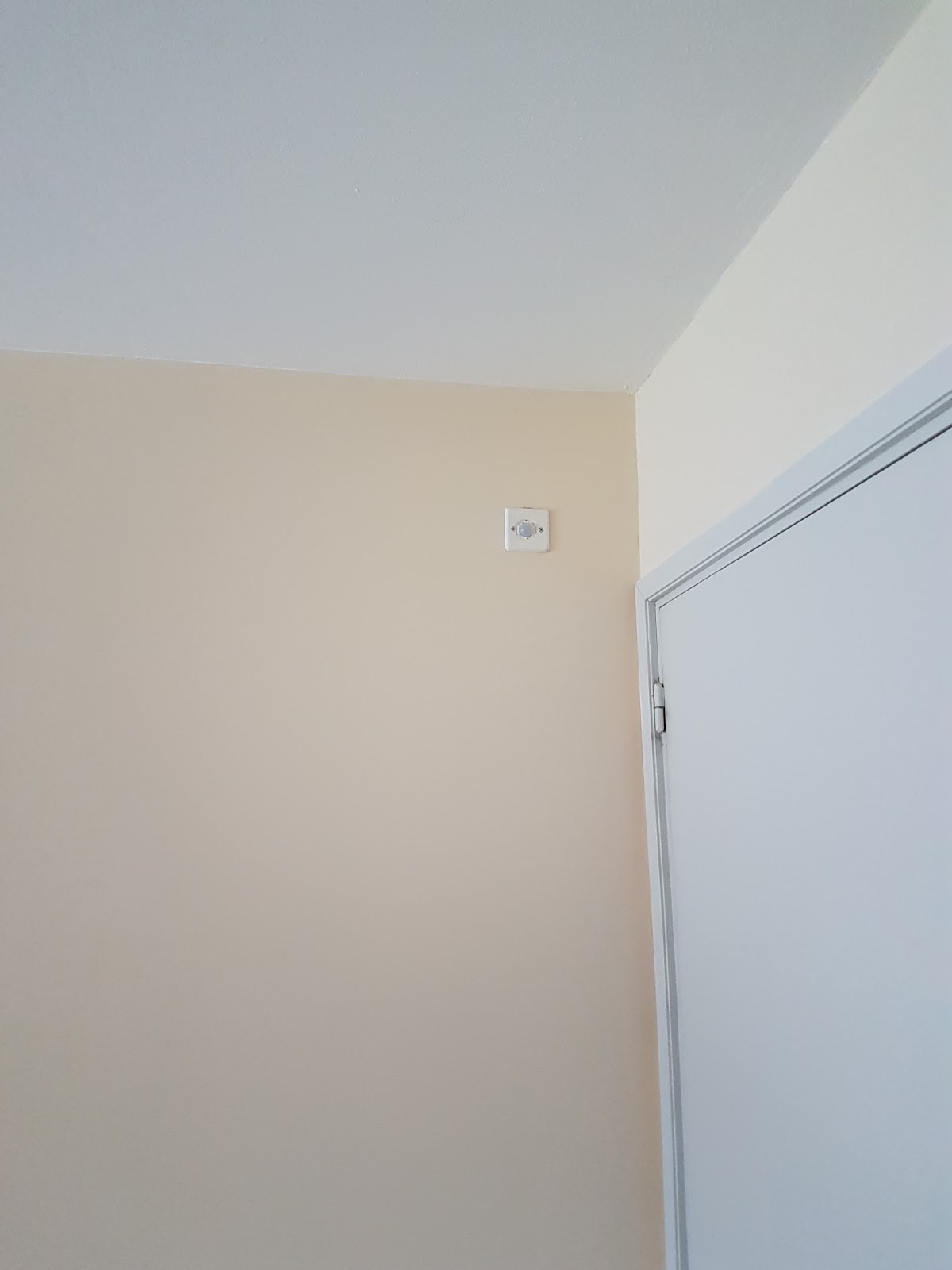 |
| Motion sensor. You can't even note it's there. |
 |
| This is where the UTP cable from motion sensor ends. |
 |
| This is the automation device. Nice uh? |
 |
| This is inside my automation box. |
 |
| This is the outlet controlled by the relay (the relay is that weird thing you can see below the outlet) |
 |
| This is the web app (part of it) |
 |
| This is the mobile app |
About electronics
I come from the software world, I am in the software world, electronics is not my thing. So, I had to learn. I'm not going to teach you electronics, but I think I can smooth your way with the things I already have learned.
Relay
I bought a box of sensors and the relay came in the package. Is a one module relay and it works fine. As is chinese, is not high quality, just a piece of crap. It worked for a while then it stopped working. I bought two relays more, one of eight modules and one of two modules (I live in Uruguay, there are very few of this kind of things here). I couldn't make them work. Then I read that some relays are active low and you have to use a transistor to send no voltage (instead of sending 3.5) to activate them. It was too much electronics for me, so I abandoned my project for some time. Then I came back and repaired the one module relay using a piece of cable, as you can see in the next image (I was illuminated that day):

Here you can see the Web and mobile apps UI: Apps UI
If you are a software developer, engineer, etc., you know at the end this is about ones and zeros. In electronics ones and zeros are represented with voltage: more than 3.5v is 1, less than that value is 0.
So what you have to do? Check the pin to see if the value is 0 or 1 (input) or send to the pin the value 1 or 0 (output). You can read documentation about this in the Raspberry PI site.
Regarding to my case in particular, the motion sensor (PIR sensor, in fact) is the easy part, and the light sensor the hard. The relay can be a pain in the ass, depending on the type of relay you have.
PIR Sensor
This sensor works with 3 cables: one for ground (-), one for voltage (+), one for signal. I'm using UTP cable so I chose 3 either colored cables. The important cable here is signal, you are going to connect this cable to some pin in the raspberry (let's assume pin 18) and then you have to check the value of that pin (1 or 0) to know if some movement is detected.
There is a screw in the sensor used to regulate the time the signal is detected. The longest time the signal is detected, the longest time you receive 1 in the pin. In my case, as I want to handle the behavior in my code, I regulated the screw to the shorter time (about 3 seconds) and I adjusted my code to ignore the repeated signals.
There is another screw to calibrate the sensitivity of the motion detection. I adjusted this to the maximum.Relay
I bought a box of sensors and the relay came in the package. Is a one module relay and it works fine. As is chinese, is not high quality, just a piece of crap. It worked for a while then it stopped working. I bought two relays more, one of eight modules and one of two modules (I live in Uruguay, there are very few of this kind of things here). I couldn't make them work. Then I read that some relays are active low and you have to use a transistor to send no voltage (instead of sending 3.5) to activate them. It was too much electronics for me, so I abandoned my project for some time. Then I came back and repaired the one module relay using a piece of cable, as you can see in the next image (I was illuminated that day):

Connecting the relay is as easy as connecting the PIR sensor. One cable for ground (-), one for voltage (+), one for signal. You will send 1 to activate the relay and 0 to deactivate it.
On how to connect the electricity to the relay, is similar to connecting a switch:
You have two cables in the outlet, one you let intact, and one you are going to cut. Now that you have cut it, the circuit is open. Connect one of the cut parts in the NO (normally open) slot in the relay and the other part in the common slot (normally the one in the middle). When you send 1 through the signal cable the circuit is closed, when you send 0 the circuit is opened, just as if you have used a switch with your hand.
Photoresistor
A photoresistor (or light-dependent resistor, LDR, or photoconductivecell) is a light-controlled variable resistor. The resistance of a photoresistor decreases with increasing incident light intensity; in other words, it exhibits photoconductivity.
How do we measure its values with the Raspberry? we need to build a circuit using a capacitor. A capacitor is a passive two-terminal electrical component that stores electrical energy in an electric field. If you don't know about electronics, as me, it's easy to understand how we are going to use the capacitor with a parable:
Let's suppose the capacitor is a bucket that we are filling with water (the electricity). While the bucket is being filled the flow of water is stopped at the other side of the bucket (so we have a 0 at the other side). Once the bucket is full, the water continue flowing at the other side (now we have 1 at the other side of the bucket). After a while the bucket is emptied, so we have to fill it again and the cycle continue the same. The time you need to fill the bucket depends on the size of the bucket (the same occurs with the capacitor).
The photoresistor is like a faucet in this example. When the faucet is more open, there's more water in the circuit and the bucket is filled quicker, and vice versa. So, we know the bucket is full when there is water at the other side of the bucket in the circuit (value is 1), and we know that the time we need to fill the bucket depends on how open is the faucet (the value of the resistence). If we measure the time we need to fill the bucket we know how open is the faucet, and as our faucet is more or less open depending on the light (is a photoresistor), using this time we know if the environment is lit or dark (ta da!).
The code
This isn't a Django tutorial so I wont explain how I have developed that part of the solution (it brings nothing new).
What I'm going to share is the code that makes the automation work (this is what matters).
You have to configure the daemons in Linux using crontab. Here you have the configuration:
@reboot /var/www/raspberry/pir_sensor.py
* * * * * /var/www/raspberry/light_sensor.py
Here you can see the Web and mobile apps UI: Apps UI
i have a masters degree on electrical engineering, so i just got this from wish https://www.wish.com/search/bathroom%20light#cid=5803a65c98bbda211621ca6b
ResponderBorrar:) im jokin btw cool project its always glorious to DIY